ESP-WROVER-KIT V2 Getting Started Guide
This guide shows how to get started with the ESP-WROVER-KIT V2 development board and also provides information about its functionality and configuration options. For the description of other ESP-WROVER-KIT versions, please check Hardware Reference.
What You Need
ESP-WROVER-KIT V2 board
USB 2.0 cable (A to Micro-B)
Computer running Windows, Linux, or macOS
You can skip the introduction sections and go directly to Section Start Application Development.
Overview
ESP-WROVER-KIT is an ESP32-based development board produced by Espressif. This board features an integrated LCD screen and microSD card slot.
ESP-WROVER-KIT comes with the following ESP32 modules:
ESP32-WROOM-32
ESP32-WROVER series
Its another distinguishing feature is the embedded FTDI FT2232HL chip - an advanced multi-interface USB bridge. This chip enables to use JTAG for direct debugging of ESP32 through the USB interface without a separate JTAG debugger. ESP-WROVER-KIT makes development convenient, easy, and cost-effective.
Most of the ESP32 I/O pins are broken out to the board's pin headers for easy access.
Note
The version with the ESP32-WROVER module uses ESP32's GPIO16 and GPIO17 as chip select and clock signals for PSRAM. By default, the two GPIOs are not broken out to the board's pin headers in order to ensure reliable performance.
Functionality Overview
The block diagram below shows the main components of ESP-WROVER-KIT and their interconnections.
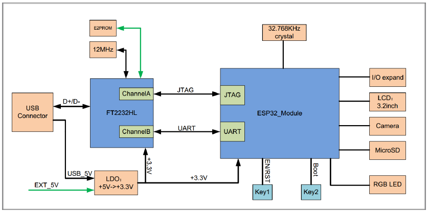
ESP-WROVER-KIT block diagram
Functional Description
The following two figures and the table below describe the key components, interfaces, and controls of the ESP-WROVER-KIT board.
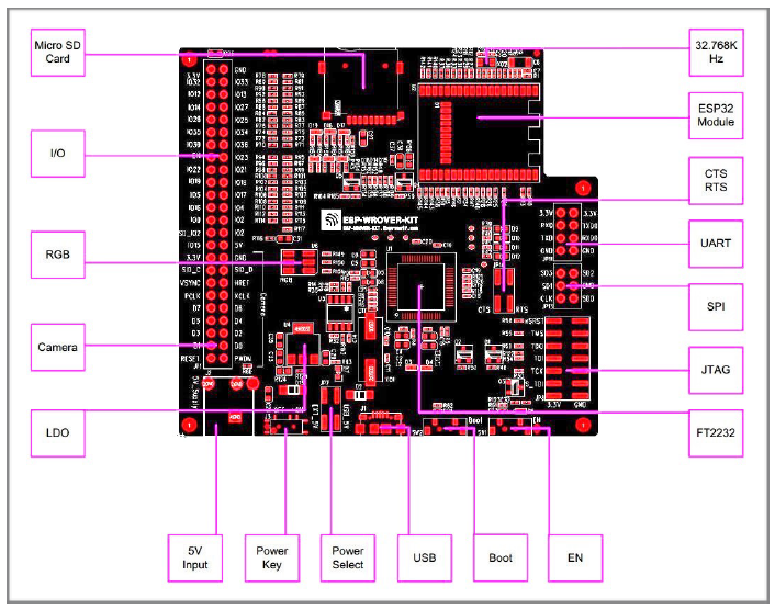
ESP-WROVER-KIT board layout - front
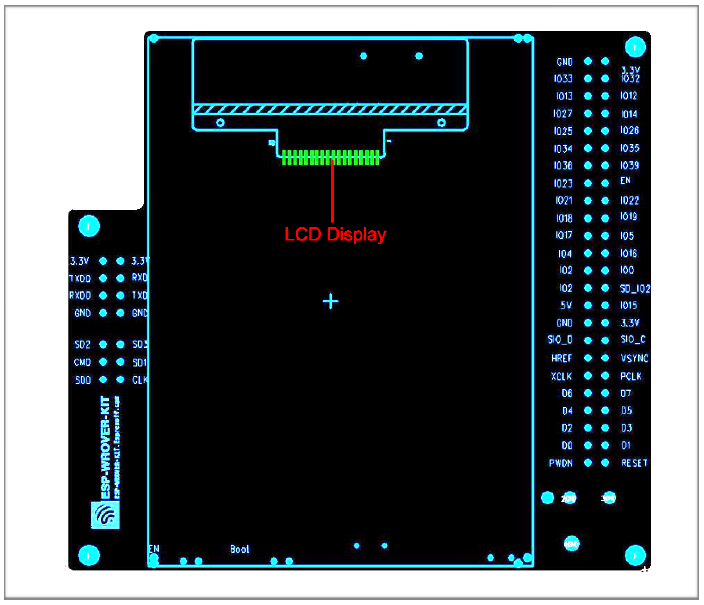
ESP-WROVER-KIT board layout - back
The table below provides description in the following manner:
Starting from the first picture's top right corner and going clockwise
Then moving on to the second picture
| Key Component | Description |
|---|---|
| 32.768 kHz | External precision 32.768 kHz crystal oscillator serves as a clock with low-power consumption while the chip is in Deep-sleep mode. |
| ESP32 Module | Either ESP32-WROOM-32 or ESP32-WROVER with an integrated ESP32. The ESP32-WROVER module features all the functions of ESP32-WROOM-32 and integrates an external 32-MBit PSRAM for flexible extended storage and data processing capabilities. |
| CTS/RTS | Serial port flow control signals: the pins are not connected to the circuitry by default. To enable them, short the respective pins of JP14 with jumpers. |
| UART | Serial port. The serial TX/RX signals of FT2232 and ESP32 are broken out to the inward and outward sides of JP11 respectively. By default, these pairs of pins are connected with jumpers. To use ESP32's serial interface, remove the jumpers and connect another external serial device to the respective pins. |
| SPI | By default, ESP32 uses its SPI interface to access flash and PSRAM memory inside the module. Use these pins to connect ESP32 to another SPI device. In this case, an extra chip select (CS) signal is needed. Please note that the interface voltage for the version with ESP32-WROVER is 1.8V, while that for the version with ESP32-WROOM-32 is 3.3 V. |
| JTAG | JTAG interface. JTAG signals of FT2232 and ESP32 are broken out to the inward and outward sides of JP8 respectively. By default, these pairs of pins are disconnected. To enable JTAG, short the respective pins with jumpers as shown in Section Setup Options. |
| FT2232 | The FT2232 chip serves as a multi-protocol USB-to-serial bridge which can be programmed and controlled via USB to provide communication with ESP32. FT2232 features USB-to-UART and USB-to-JTAG functionalities. |
| EN | Reset button. |
| Boot | Download button. Holding down Boot and then pressing EN initiates Firmware Download mode for downloading firmware through the serial port. |
| USB | USB interface. Power supply for the board as well as the communication interface between a computer and the board. |
| Power Select | Power supply selector interface. The board can be powered either via USB or via the 5 V Input interface. Select the power source with a jumper. For more details, see Section Setup Options, jumper header JP7. |
| Power Key | Power On/Off Switch. Toggling toward USB powers the board on, toggling away from USB powers the board off. |
| 5V Input | The 5 V power supply interface can be more convenient when the board is operating autonomously (not connected to a computer). |
| LDO | NCP1117(1 A). 5V-to-3.3V LDO. NCP1117 can provide a maximum current of 1 A. The LDO on the board has a fixed output voltage. Although, the user can install an LDO with adjustable output voltage. For details, please refer to ESP-WROVER-KIT V2 schematic. |
| Camera | Camera interface, a standard OV7670 camera module. |
| RGB | Red, green and blue (RGB) light emitting diodes (LEDs), can be controlled by pulse width modulation (PWM). |
| I/O | All the pins on the ESP32 module are broken out to pin headers. You can program ESP32 to enable multiple functions, such as PWM, ADC, DAC, I2C, I2S, SPI, etc. |
| microSD Card | microSD card slot for data storage: when ESP32 enters the download mode, GPIO2 cannot be held high. However, a pull-up resistor is required on GPIO2 to enable the microSD Card. By default, GPIO2 and the pull-up resistor R153 are disconnected. To enable the SD Card, use jumpers on JP1 as shown in Section Setup Options. |
| LCD | Support for mounting and interfacing a 3.2” SPI (standard 4-wire Serial Peripheral Interface) LCD, as shown on figure ESP-WROVER-KIT board layout - back. |
Setup Options
There are five jumper blocks available to set up the board functionality. The most frequently required options are listed in the table below.
| Header | Jumper Setting | Description of Functionality |
|---|---|---|
| JP1 |  | Enable pull up for the microSD Card |
| JP1 |  | Assert GPIO2 low during each download (by jumping it to GPIO0) |
| JP7 | 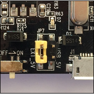 | Power ESP-WROVER-KIT via an external power supply |
| JP7 | 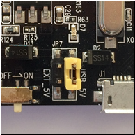 | Power ESP-WROVER-KIT via USB |
| JP8 | 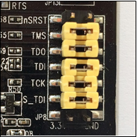 | Enable JTAG functionality |
| JP11 | 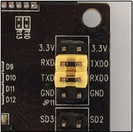 | Enable UART communication |
| JP14 | 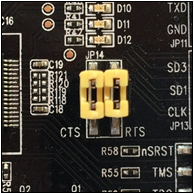 | Enable RTS/CTS flow control for serial communication |
Start Application Development
Before powering up your ESP-WROVER-KIT, please make sure that the board is in good condition with no obvious signs of damage.
Initial Setup
Please set only the following jumpers shown in the pictures below:
Select USB as the power source using the jumper block JP7.
Enable UART communication using the jumper block JP11.
| Power up from USB port | Enable UART communication |
|---|---|
| |
Do not install any other jumpers.
Turn the Power Switch to ON, the 5V Power On LED should light up.
Now to Development
Please proceed to Get Started, where Section Installation will quickly help you set up the development environment and then flash an example project onto your board.